


Guide To Writing Your First Emulator | CHIP - 8
Part - 0x02


In the first article of this series, we learned about basics of an emulator, what it does and how to think while emulating one. I hope you watched the video playlist linked there and understood how computer works under the hood. This article assumes the reader has knowledge of at least binary-hex, what are OPCodes and how are they executed, how peripherals interact etc. So now let's start with actual CHIP - 8 discussion. But before starting, I would like to remind you that CHIP - 8 was itself an emulator, so you will be writing an emulator of an emulator, let that sink in.
Note
- All the information about specifications comes from Cowgod's CHIP - 8 reference, several other articles and my own notes (which, in fact, also have information from Cowgod's reference). If you can fully understand Cowgod's reference, then you don't really need anything else for that matter and can skip this article. But if you find that information hard to grasp, this article may help in one or two.
- CHIP - 8 is referred to as as C8.
- Terms for referring to specs are used to be same as in other articles of this subject so that the reader can read this article in conjunction with them.
Specifications
In this section, we will be looking at the hardware of C8 which we need to emulate.
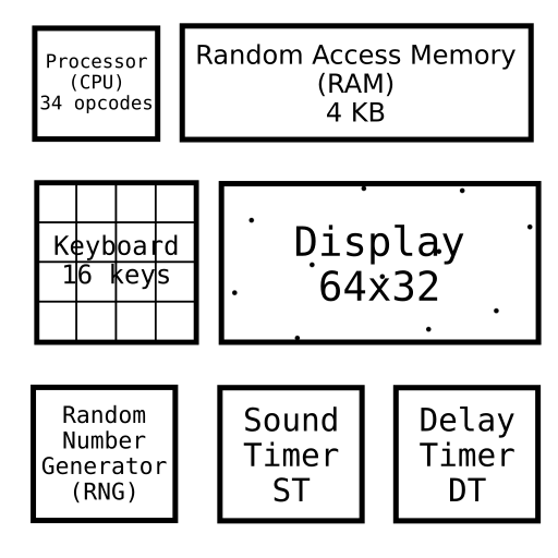
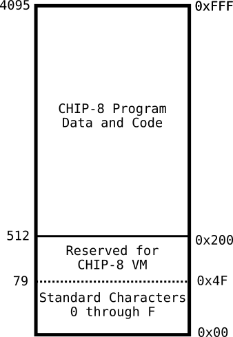
Memory
C8 was able to access 4KBs (4 Kilo Bytes = 4096 bytes), from location 0x000 to 0xfff (It is worth noting that the machine on which C8 was running could had more than 4KBs of memory. I was C8's limitation to only use the first 4KBs).
The C8 emulator resided in the first 512 bytes (0x000 - 0x1ff) of host device, i.e., just like you operating system uses a couple of GBs in your storage and you can't use that storage for storing files, it's the same thing. The code for C8 and its core functionalities was stored in this location, and can't be used by the programs.
Most C8 programs use the memory start from location 0x200 (512) itself, but some also start from 0x600 (1536) (intended for ETI 660 computer).
Memory Map
Implementation (click to expand)
Memory is quite easy to implement. You can define an unsigned char of size 0xfff (4096 bytes), as it is of 1 byte and work on it from address 0x200 or 0x600 depending on the ROM your are using. If your programming language doesn't support 1 byte variables, you can also use an array of whatever is the smallest byte size it support. The idea is using as less resource as possible in your host machine while writing an emulator.uint8_t memory [0xfff] = {0};
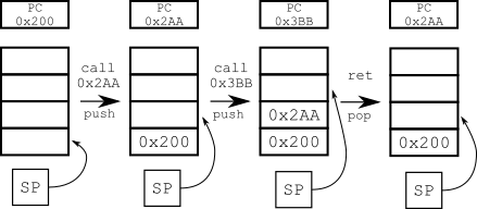
Stack
An array of size 0xf of 2 bytes. When a subroutine (function) is called, C8 stores the address of current OPCode in the stack, so that when we return from that function, we know where we left off.
Implementation (click to expand)
General implementation would be to declare an array of size 16, having element size as 2 bytes. You can also use the inbuilt Stack data structure, but the array implementation is my favourite.uint16_t stack [16] {0};
Random Number Generator (RNG)
Generates a random number of 1 byte (0 - 255).
Registers
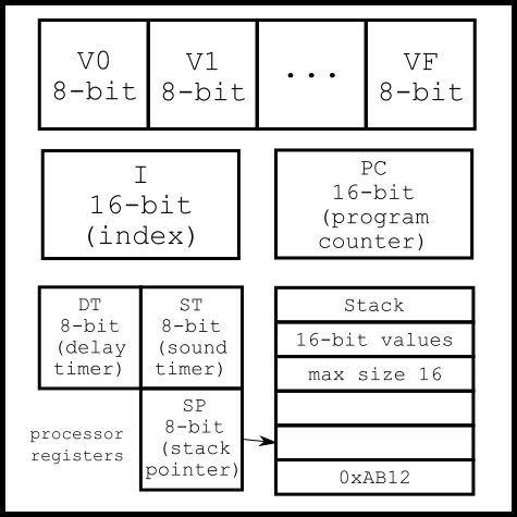
Registers are special purpose memory blocks, built directly into the processor. Reason for having registers to store information, even though we have memory for that matter, is that registers are located very close to the CPU and thus accessing them is very fast compared to RAM (as it's all electric signal after all). C8 has 4 types of registers.
General Purpose Registers
C8 has 16 general purpose registers of one octet (1 byte). We will be referring to these as Vx (where x is a hex digit 0x0 - 0xf). Vf is used as a flag, so programs shouldn't use it.
Special Purpose Registers
There are two special purpose 1 byte registers, namely Delay Time and Sound Timer (DT and ST). When they are non-zero, they automatically decrease at 60Hz (60 times per second).
Delay Timer - When it is non-zero, it simply decrements by 1 at 60Hz (important to note that this should always be 60Hz irrespective of the frequency that your emulator is running on).
Sound Timer - Same as DT, but sound plays whenever it is non zero and stops when it reaches zero. C8 devices had a monotonic audio, so your implementation can simply play a beep as sound. You can decide the frequency of this beep.
Pseudo registers
A 2 byte register Program Counter (PC) which stores the address of currently running OPCode, i.e., while emulating the CPU, we run the OPCode that is stored in memory location PC, execute it, and change PC accordingly. We generally increment it, but there can be other cases like when we return from a function. We will see this in the CPU section. Note that if memory block at PC contains an OPCode that sets PC to its original value, then it will cause an infinite loop. This is used by some programs when they exit.
A 1 byte register Stack Counter (SP) which stores the last stored element in the stack. When a function returns, we set PC to the top element of Stack and decrease SP.
The I
C8 has a 2 byte register, generally used for storing memory addresses. We will refer to it as I.
Implementation (click to expand)
You can either make class for all the registers or declare individual variable. I prefer the latter.uint8_t V[0xf] {0x0}; uint8_t DT {0x0}; uint8_t ST {0x0}; uint8_t SP {0x0}; uint16_t PC {0x200}; // Initialize this with the memory location you started to put the OPCodes in. Default is 0x200 (as discussed above). uint16_t I {0};
Keyboard
C8 computers had a 16 key hexadecimal keyboard (keys marked 0-F). Any C8 implementation will need a mapping which lets the user give input to programs. The original keyboard looked like this.
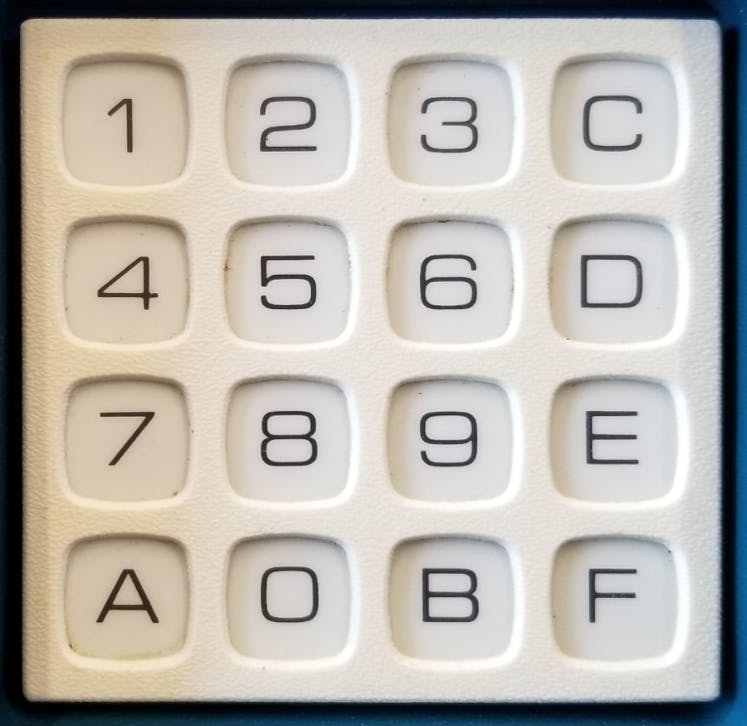
The COSMAC VIP keyboard
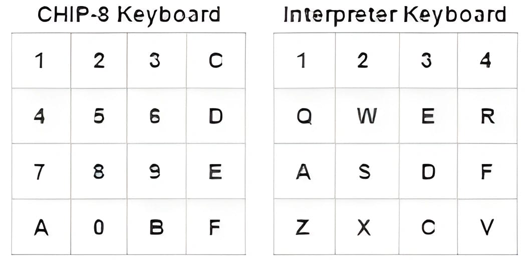
Normally, C8 emulators use following mapping
Display
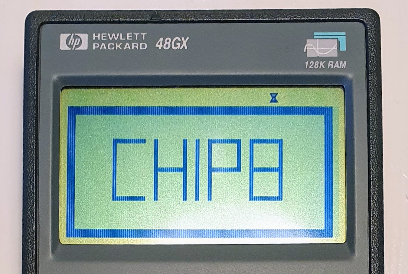 CHIP - 8 on HP48
Original implementations of C8 had a monochromatic display of 64 * 32 pixels, i.e., a display having 64 pixels per row and 32 pixels per column. Since it is monochromatic, a pixel will either be off, or it will be on and glow in a single color. This makes the screen look like a background, painted on some spots.
You have the option to chose these foreground and background colors. (A shade of green on some shade of grey looks nice in my opinion 🌝
Sprites
C8 stores some standard sprites (the hex numbers 0x0 - 0xf) in memory beforehand. Each sprite is 5 bytes long. But how does that work ? Let's try to understand this visually.
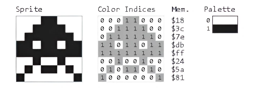
Say we have an array of short integers as [0x18, 0x3c, 0x7e ......] (as in the picture), if we look at the binary representation of these numbers, stacked one after the other and paint 0s with one color and 1s with another, we can see a patter emerging as in the above picture.
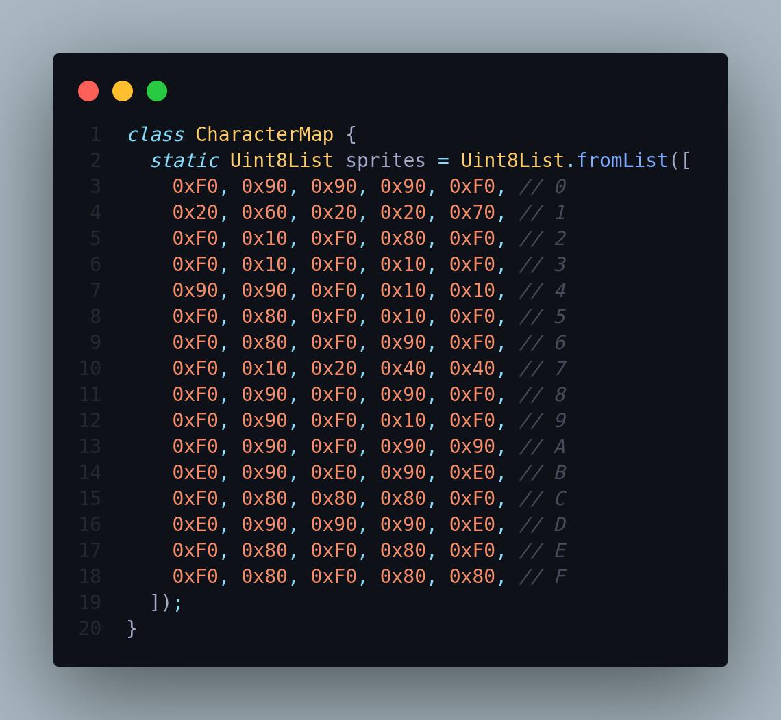
In C8, we use similar approach. We use 5 bytes, each byte representing a row, to represent a sprite. One thing to note is that in C8, we only store information about the sprite in the 4 most significant bits (MSB) of the byte. Last 4 are not used. So, 'A' can be represented as [0xF0, 0x90, 0xF0, 0x90, 0x90]. How ? Write these numbers in binary, stacked one after other and see.
We need to store all the hex digits, 0-F in emulators memory. Since the first 0x200 bytes of memory are reserved for the interpreter itself, we generally store them in memory location 0x000 - 0x04f (16 sprites * each takes 5 bytes = 80 bytes = 0x4f) as you can see in the picture about memory above. You can directly use the below mapping
More info about display buffer and how to draw things in the section about OPCodes.
Implementation (click to expand)
I like to store the display buffer as a 2D array. But how to represent a pixel ? It depends on you. You can use a character where ' ' (space) represents that the pixel is off and '0' (or any non-space character for that matter) represents that the pixel is on. Or you can use an integer / short integer, where 0 represents off and 1 represents on.But as you may see, these implementations waste a lot of memory, because all you need is 1 and 0, which can be represented in a single bit, and we are using 8 bits to represent that. This wastes 64x32x8 - 64x32x1 = 14336 bits (1792 bytes or 1.75 KBs) of memory. To avoid this we can use an array of
unsigned long longs. A long long is of 64 bits (exactly what we need) and having 32 of these will be enough to represent our display. We can use bit manipulation to get the state of pixel at (x, y).unsigned long long display_buffer [32] {0}; But there's a even better way in C++. The default implementation of
vector<bool> in C++ uses only a single bit for each value, so a vector<vector<bool>> display_buffer (32, vector<bool> (64, false)); only takes 64x32 bits of memory. If your languages doesn't have such compression, you can use the 64 bit int representation and modify bits accordingly.
The CPU
This is where the fun lies. We will be looking at each of the instructions that C8 supports, what they do and how to emulate them. C8 supports a total of 36 Operation Code (OP Codes, which basically means an operation that a CPU performs), ranging from clearing the screen and drawing sprites, to generating random numbers and performing math. We will look into them in the next article of this series. Till then, why don't you try making the sprite sheet for 420 🌝 ?